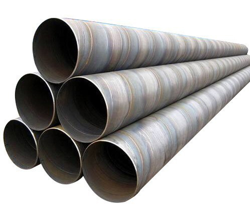
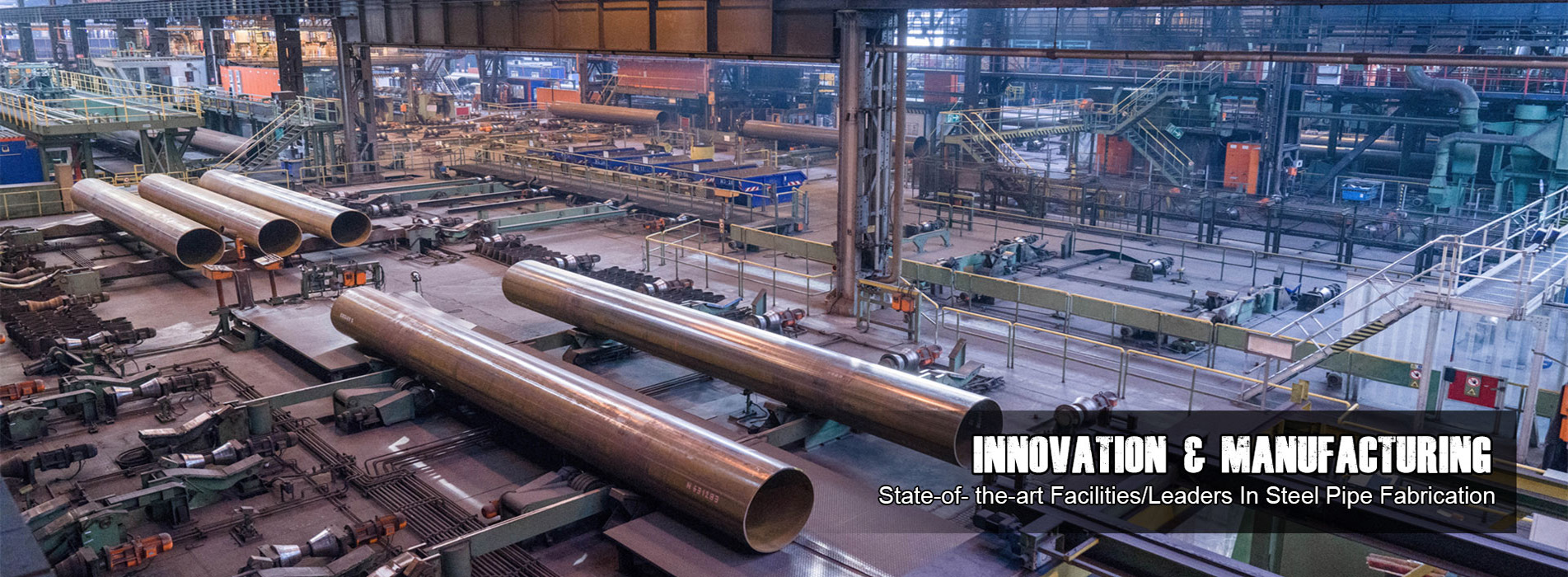
Welded steel pipe is created using a flat steel plate or steel strip, and its manufacturing process results in a seam on its body. Specifically, when welded steel pipe is manufactured, a steel plate or strip is bent and subsequently welded into either a circular, traditional pipe shape or a square shape.
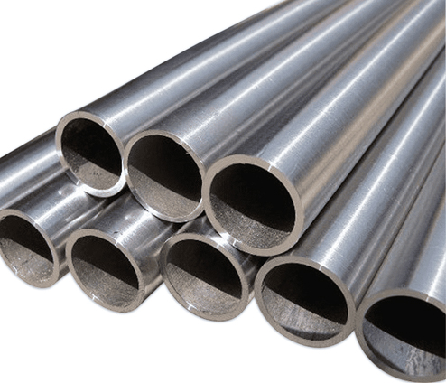
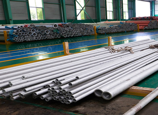
Seamless steel pipe is a circular pipe having a hollow section and no seams around it. The seamless steel pipe is made of carbon steel, alloy steel, stainless steel ingot or solid tube blank, and then is made by hot rolling, cold rolling or cold drawing. Seamless pipes are considered superior to welded pipes as they are built using monolithic steel billets, with intrinsic mechanical strength, without seam welds.
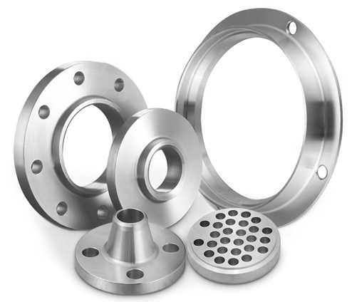
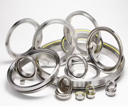
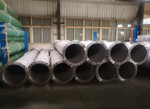
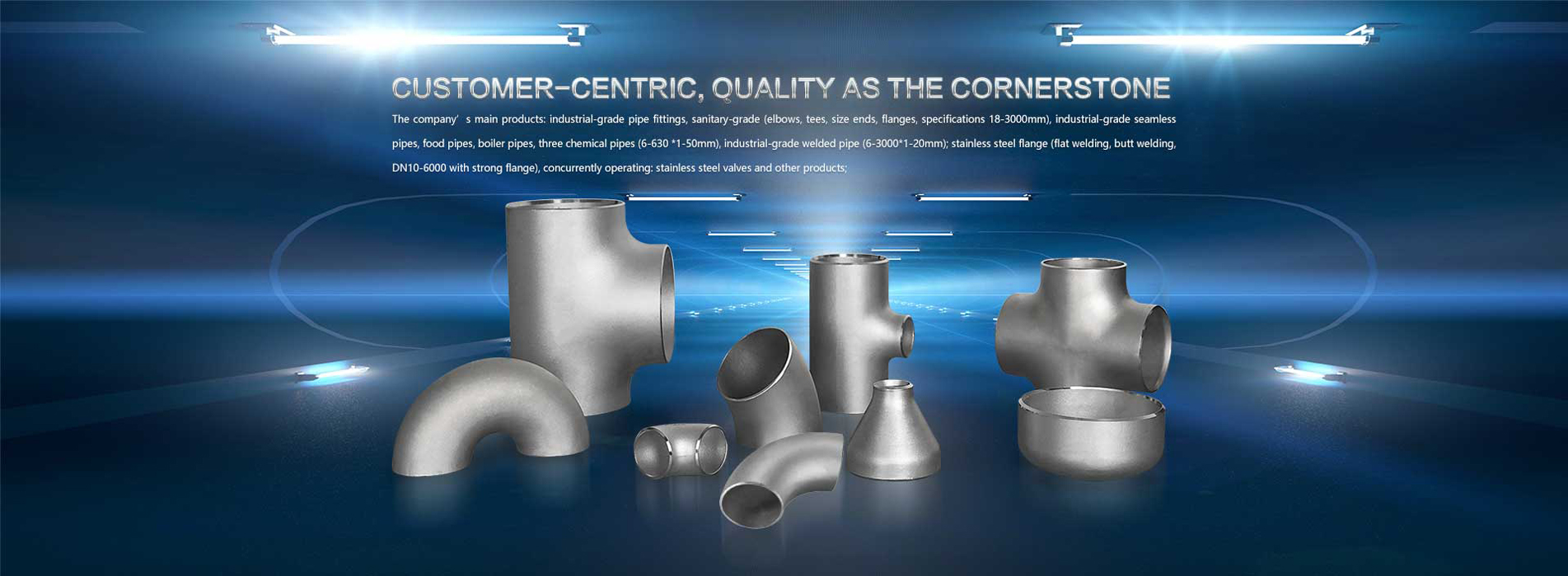
Flange is the part that connects the pipe to the pipe and is connected to the end of the pipe. There are holes in the flange and bolts make the two flanges tightly connected. The flange is sealed with a gasket. And flanges are usually welded or screwed.
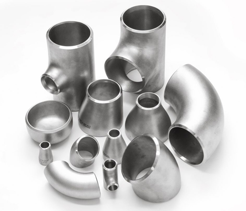
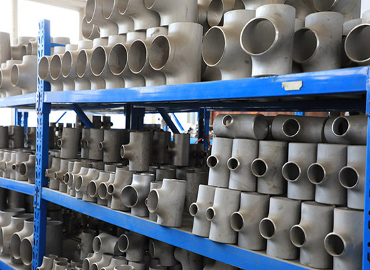
Fittings are parts that connect the pipes and aid in changing the direction of the flow or the pipe size or connecting different components for instance elbow fitting, tee fitting, eccentric reducer, and compression fitting, etc.
Ecoway Steel is a Chinese company that specializes in manufacturing a wide variety of top-notch materials for gaskets. These gaskets can be used in various industries such as oil and gas, pulp and paper, chemical, and mining. Our company provides the latest technologies and solutions for gaskets that can withstand even the harshest environments.
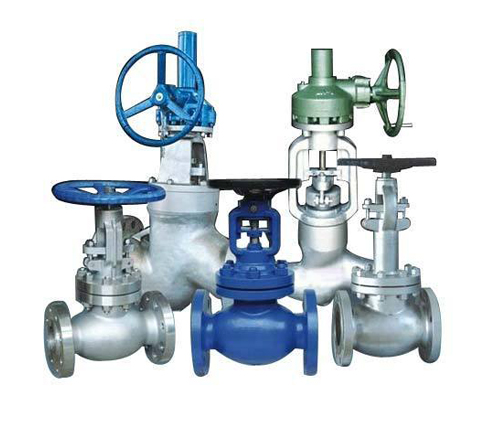
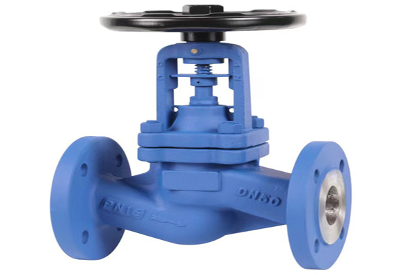
Valve is a control component in the pipeline fluid conveying system, which is used to change the passage section and the flow direction of the medium, and has the functions of diversion, cut-off, throttling, check, diversion or overflow and pressure relief. Valves used for fluid control range from the simplest shut-off valve to various valves used in extremely complex automatic control systems. Valves for industrial pipelines. It can be used to control the flow of various types of fluids such as water, steam, oil, gas, mud, various corrosive media, liquid metals and radioactive fluids. The working pressure of the valve can be from 0.0013MPa to 1000MPa ultra-high pressure, and the working temperature can be c-270°C ultra-low temperature to 1430°C high temperature.
Ecoway Steel Group

year established

COUNTRIES

square meter
How does the Bellows Seal Globe Valve work? Turning the actuator or the handwheel, the stem will rise along with the disc away from the seat, which allows the material to flow through the valve. But when you turn the actuator in the opposite direction, the stem will push the disc against the seat. So, it will block the path for materials to flow through. While the material goes through the valve, the other components are also working for smooth performance. To illustrate, the bellow stretches and folds to keep the material from being carried out around the stem as it moves. 5 Types of Bellows Seal Globe Valve Flanged Bellows Seal Globe Valve This bellow seal globe valve has a connection that features raised flat rims on both ends called flanges. This makes it easy to install and remove for regular maintenance or repair. Y Pattern Bellows Seal Globe Valve Notable for its unique “Y”-shaped body. As a result, the material may travel more straight across the valve than by the other types. This will help reduce pressure drops because the material does not need to change direction inside the valve. Extended Bellows Seal Globe Valve These globe valves consist of longer bellows than the other types. The expanded bellows increase the valve’s protection from potential hazards such as leaking, particularly for high-temperature and high-pressure applications. Welded Ends Bellow Seal Globe Valve Its bellow seals’ ends are already tightly attached to the stem. So, it had a permanent and strong seal unlike other valves, making them suitable for high temperature and high pressure working environments. Socket-welded Bellows Seal Globe Valve It has a circular aperture at both valve ends where the pipes can be placed directly. This results in an effective, non-leaking connection. What are the Advantages and Disadvantages of Bellow Seal Globe Valve? Like other valves, it also has advantages and disadvantages to take note of, such as the following: Advantages Disadvantages Have flexible metal bellows that prevent leakage around the stem, unlike other regular globe valves. The bellows is another component that can be damaged from different factors, like improper handling. The stem packing will continue to protect the valve from leaking in case the bellows are damaged. This increases the durability of this valve. It includes more components than other valves, which involve a bellows seal and stem packing. As a result,the amount of components required and the difficulty of installing the valve increase. Its high-quality materials are less vulnerable to corrosion, making them ideal for hazardous materials that are often used in most industries. Its complex design and high-quality materials make them more expensive to manufacture than other valves. How to Choose the Best Bellows Seal Globe Valve Manufacturer? There’s a lot of factors to consider when choosing the right bellow seal globe valve manufacturer. Analyse the manufacturer’s experience in the field of creating valves and their product range. Longer experience in manufacturing and having a wide product range will ensure they can meet the customers unique requirements for application.
read moreBellows seal globe valves have the ability to create reliable leak-free seals in high-temperature and high-pressure environments. As a result, they are crucial items in different industries like chemicals and gas for their smooth and safe operation. Continue reading to learn more about bellows seal globe valves, including their main components and types. What is a Bellow Seal Globe Valve? A bellow seal globe valve safely controls and manages the flow of materials like fluids and gases inside a pipeline. It’s because it is an industrial item that uses multiple seals to protect its valve from leaking. An example of its seal is the one around the stem. This makes them commonly used in industries like oil, gas, and chemical for their operation. These factories’ environments have a higher chance of dangerous leakage and fire due to the toxic materials it handles, which can cause safety concerns. The Main Components of Bellows Seal Globe Valve The bellows seal globe valve is built up of multiple components, including the stem, body, disc, bellows seal, packing and bonnet,. Each of their important functions in the bellow seal globe valve will be further explained below. 1. Disc This bellows seal globe valve’s part is the main sealing component and the one that is attached to the stem. The stem lifts the disc from the seat when the valve is open, allowing the material to go through the passage. But when the valve is closed, the disc is pressed against the seat to prevent the material from going through the pipes. 2. Stem This is the component that is connected to the bellows seal globe valve’s disc actuator, which lets the material go through the pipe or prevents it. When the handwheel turns, the stem moves the disc up or down, and this lets the valve either open or close. 3. Body The bellows seal globe valve body is the main structure that holds all the other components inside to control the materials passing through it. It is designed to be used in high-temperature and high-pressure environments. One of the reasons is because it is made from durable materials that can often handle up to 2500 psi. 4. Bonnet The bonnet protects the valve’s stem and packing from outside environmental factors like dust and moisture, as well as preventing leaking. This is usually fastened or welded in the valve’s body to maintain its structural integrity and achieve a smooth operation. 5. Packing This serves as the valve’s extra seal around the stem, which increases its structure’s safety and reliability. When the bellow seal gets damaged, the packing becomes the additional barrier that blocks the materials inside the pipe from leaking. 6. Bellow Seal Bellow seals are components that are shaped into a set of rounded folds and wrapped around the stem. This is also made from strong materials that can be designed to be flexible and effective seals, such as: Hastelloy Stainless steel Flexible graphite The bellow seal can expand and shrink according to the changes in pressure and temperature in the entire pipe structure. Therefore, it protects the valve stem while it moves and ensures safe operation.
read more
Introduction Pneumatic actuator gate valves are vital components in industries that require efficient control of fluid flow. These valves provide reliable and precise regulation of liquid or gas flow through pipelines. In this comprehensive guide, we will delve into pneumatic actuator gate valves, including their definitions, types, working principles, and key features. This information will help you gain a better understanding of these products and their applications. Definitions and Types of Pneumatic Actuator Gate Valves Pneumatic actuator gate valves are valves that use a pneumatic actuator to control the movement of a gate or wedge inside the valve body. These valves are designed to control fluid flow by raising or lowering the gate to open or close the flow passage. They come in various types, including: Rising Stem Gate Valves: Rising stem gate valves have a stem attached to the gate, which rises or lowers as the valve opens or closes. This design provides a visual indication of the valve’s position and allows for manual operation even when the actuator is not engaged. Non-Rising Stem Gate Valves: Non-rising stem gate valves have a gate that moves up and down within the valve body without the stem rising or lowering. These valves are ideal for applications with limited vertical space. Working Principles of Pneumatic Actuator Gate Valves Pneumatic actuator gate valves operate based on the principle of raising or lowering a gate or wedge to control fluid flow. When the pneumatic actuator receives a signal, it engages the valve, moving the gate to open or close the flow passage. The actuator provides precise control, allowing for accurate adjustments to regulate flow rates. If you want to know more about the Working Principles of Pneumatic Actuator Gate Valves, please click here. Key Features and Advantages of Pneumatic Actuator Gate Valves Pneumatic actuator gate valves offer several features that make them advantageous in fluid control applications. Some key features include: Excellent Flow Control Pneumatic actuator gate valves provide precise control over fluid flow, allowing for accurate adjustments and modulation of flow rates. This makes them suitable for applications that require precise flow regulation. Bi-Directional Flow Gate valves are capable of handling bi-directional flow, allowing for flow control in both directions. This versatility makes them suitable for various applications. Quick Operation These valves have fast response times, enabling quick opening and closing of the valve, which is crucial in situations that require immediate flow control. Tight Shut-Off Pneumatic actuator gate valves provide tight shut-off, minimizing leakage and ensuring reliable sealing. Applications of Pneumatic Actuator Gate Valves Pneumatic actuator gate valves find applications in industries such as oil and gas, water treatment, chemical processing, and more. They are commonly used in systems that require on/off control of flow, isolation of sections of pipelines, or regulation of flow rates. Conclusion Pneumatic actuator gate valves play a crucial role in ensuring precise fluid control in various industrial applications. With their robust construction, efficient operation, and reliable sealing, these valves provide an excellent solution for managing fluid flow in diverse settings.
read more
If you’re looking for a valve to control the flow of fluids, you’ve probably heard about V notch ball valves. These valves are highly efficient, and they can be used in a variety of industries. When you’re looking for the right valve for your application, you’ll want to learn all you can about the V notch ball valve. This valve type is an excellent choice for fluids that require precise flow control and zero loss of motion. It’s designed to work with pulp, paper stock, and suspended solids and is a great option for fluid control. You’ll get accurate control and a non-clogging design that can withstand even the toughest fluids. If you want to know more about it continue reading this article. What Is V Notch Ball Valve? V-notch ball valves are designed for high-capacity, straight-through flow control in a variety of fluids. They are particularly useful in processes involving pulp and paper stocks and are also well-suited for liquids with suspended solids. A V-notch ball valve has a small operating torque and can be fitted in a variety of applications. This type of valve is used in a variety of industrial applications. It has an exclusive design and is available in 15-, 30-, 45-, 60-, and 90-degree V-notch angles. It features a balanced flow characteristic and is an affordable alternative to much larger, more expensive control valves. These valves have several advantages over other types of ball valves. Flow control is the most common requirement for V-notch ball valves. A low-angle V-port provides better control over low-flow rates, and a narrow-slot valve offers linear flow control at the same percentage. However, narrow-slit valves are more prone to cavitation in the flow, which increases localized pressure and the possibility of a cavitation-prone zone. Its body is perfect for erosive and viscous fluids and slurries with entrained solids. Applications include the power industry, paper industry, sewage treatment plants, and petroleum refineries. These valves feature a unique trim, which eliminates cavitation. This trim is particularly useful for applications involving viscous, erosive fluids and slurries. Applications of a V Notch Ball Valve It is a great valve option for a variety of applications, such as those found in pulp and paper production. Its integral design eliminates leak paths and provides greater rigidity against fluctuating pipe loads. Its flange and wafer connections also help eliminate leak paths. One of the most common uses for a V notch ball valve is pipeline control. These valves have a V-Notch on the inside of the valve body, which makes them ideal for many different applications. Because of their V-Notch, these valves offer superior flow control and can be found in smaller sizes than globe valves. They also tend to be less expensive than their global counterparts. Another common use for a V notch ball valve is for tight shut-off. Because of their simple design, check valves operate with no human interaction. They work by measuring the velocity of a flowing fluid. The higher the velocity of the flow, the more the valve will open. These valves are also commonly used in wastewater management systems. A V notch ball valve is a great choice for any application where you need to regulate the flow. This versatile valve is suitable for high-temperature and pressure applications. This non-clogging and high-capacity valve are mostly used in pharmaceutical, beverage and food industries, cosmetic industries, etc.
read more


No.1633, Binhai Road, Wenzhou Economic Development Zone, Wenzhou, China
 IPv6 network supported